Hello,
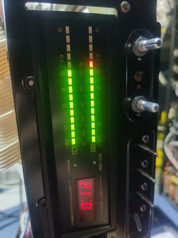
The 20V you measured at VR301/VR401 are causing the LEDs to lit.
Now we need to find, why you have there 20 V. I think, we are close to the solution.
Because you measure all eight PINs of IC101 also 20V, the ground connection (GND) is missing or you created a short between +20 V supply and the black wire which connects PIN4 of IC101 with ground (GND).
IC101 is supplied with 20 V at its PIN 8 only. PIN 4 of it must be on GND. However, you measure 20 V also on PIN4 of the IC. That means that it is not on GND, connection through the black wire from (E) is interrupted or you have the other end of that wire accidentially connected with 20 V.
The ground connection (GND) is the black wire on your photograph which is soldered into the board at point (E). The black wire at point (E) is connected with PIN 4 of IC101 and thus represents GND for the IC.
Your fault is likely on the other end of this black wire (originating from point (E)), where it is soldered into the board next to diode D531. I guess, that you got a short (unwanted connection) there to the +20 V of board PIN 528 which is directly next to it. I have marked this possible short in red. Please inspect the solder side of the board closely in that area.
If everything is correct, the black wire is firmly soldered into both points (E) and you will measure zero Ohm between PIN 4 of IC101 and the CD360 metal chassis. There must be no short (red) from the other end of the black wire (close to D531) to board PIN 528 or its printed wiring connection. (Please click on the picture to enlarge it).

Please be aware of a printing error on the SABA schematic (solder side), where the "other end" of black wire from (E), next to diode D531) is wrongly indicated as (J) instead of (E). The printing on the board however (E), is correct. I have corrected the printing error in my picture already.
I have indicated the connection of the black wire GND connection in yellow color for easier visibility. I also marked the problem zone where the +20 V PIN 528 is next to the solder point of the GND wire and where I suspect a short.

(Please click on the picture to enlarge it.)
Best Regards
Reinhard
The 20V you measured at VR301/VR401 are causing the LEDs to lit.
Now we need to find, why you have there 20 V. I think, we are close to the solution.
Because you measure all eight PINs of IC101 also 20V, the ground connection (GND) is missing or you created a short between +20 V supply and the black wire which connects PIN4 of IC101 with ground (GND).
IC101 is supplied with 20 V at its PIN 8 only. PIN 4 of it must be on GND. However, you measure 20 V also on PIN4 of the IC. That means that it is not on GND, connection through the black wire from (E) is interrupted or you have the other end of that wire accidentially connected with 20 V.
The ground connection (GND) is the black wire on your photograph which is soldered into the board at point (E). The black wire at point (E) is connected with PIN 4 of IC101 and thus represents GND for the IC.
Your fault is likely on the other end of this black wire (originating from point (E)), where it is soldered into the board next to diode D531. I guess, that you got a short (unwanted connection) there to the +20 V of board PIN 528 which is directly next to it. I have marked this possible short in red. Please inspect the solder side of the board closely in that area.
If everything is correct, the black wire is firmly soldered into both points (E) and you will measure zero Ohm between PIN 4 of IC101 and the CD360 metal chassis. There must be no short (red) from the other end of the black wire (close to D531) to board PIN 528 or its printed wiring connection. (Please click on the picture to enlarge it).
Please be aware of a printing error on the SABA schematic (solder side), where the "other end" of black wire from (E), next to diode D531) is wrongly indicated as (J) instead of (E). The printing on the board however (E), is correct. I have corrected the printing error in my picture already.
I have indicated the connection of the black wire GND connection in yellow color for easier visibility. I also marked the problem zone where the +20 V PIN 528 is next to the solder point of the GND wire and where I suspect a short.
(Please click on the picture to enlarge it.)
Best Regards
Reinhard
Dieser Beitrag wurde bereits 14 mal editiert, zuletzt von „oldiefan“ ()


