
1. Insert the plug into the power supply (at this time all the indicators are off and there is no sound);
That is correct! The unit is now plugged onto Mains but not yet switched on. None of the two trafos is attached to mains power at this stage yet.
2. Press the power switch of 9141 (2 red LED lights near the power switch are on, one of the LED lights flashes), the others have no response and no sound;
That is correct! The unit is now switched on with its auxiliary power supply unit, but not yet with its main transformer. Thus the unit is in stand by (idle state). It is ready to receive signal from remote control or from any of the unit's signal keys Nos. 9-17 at the unit's front. But the functions are not yet active unless such key is pressed.
3. Press the FM button, all the indicator lights will light up for only 1 second, and all the indicator lights will automatically go out. The sound of the relay switch can be heard in this 1 second, and there is no other response.
That is correct! When pushing the FM button (FM button, No. 9, is one of the signal keys) the unit will switch on fully. The power relay RS653 kicks in and the mains transformer is powered up (that's the relay you are hearing). During this powering up, the LEDs all light up for a moment and then go out, except the LED right above the FM button, which will remain on.
All you wrote so far indicates that your unit powers up exactly as described in the SABA 9141tc owner's manual.
In case, after you pushed the FM button and the unit shuts on but there is no FM reception and even the FM-LED does not light, you might have the MONITOR button pushed. As written in the owner's manual the MONITOR button overrides all other functions and thus deactivates also fm. With other words, if the unit appears not to work, it could be due to the MONITOR button being "on".
Please check that the MONITOR button (no. 19) is not pushed (must be off).
Please show a photograph of the front with all LEDs, after you powered up the unit after you pushed the power-on button und then pushed the TAPE 1 key (No. 17); MONITOR off.
Please show another photograph after you powered up and then pushed the FM button (No. 9), MONITOR off.
If the unit does not react to any keys after it has been powered on with the FM button (and MONITOR is shut off), the unit's power supply board may not supply the required voltages. In that case please measure the voltage at the following test points (indicated on the main board's back side) against chassis ground (after you have switched on the unit with the "power on" button and then with the FM button and you have heard the power relay kicking in):
J1 (shall be 20V DC)
H5 (shall be 15V DC)
Regards,
Reinhard
Dieser Beitrag wurde bereits 10 mal editiert, zuletzt von „oldiefan“ ()
 '>
'> ' data-cke-saved-src='
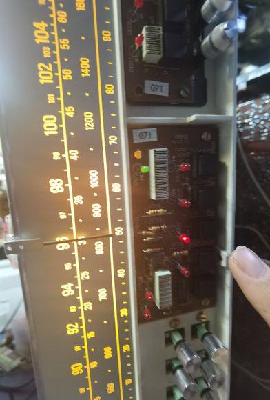 ' data-cke-saved-src='
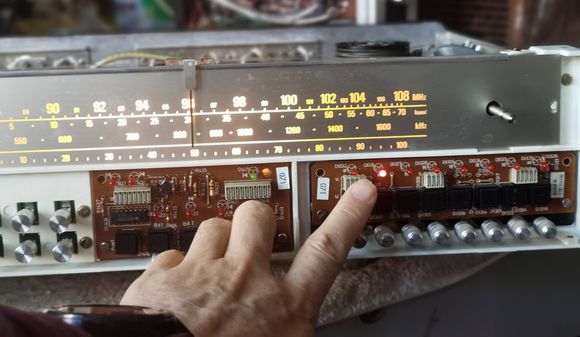 ' data-cke-saved-src='
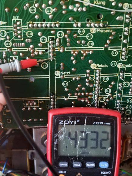 ' data-cke-saved-src='
 ' data-cke-saved-src='
 ' data-cke-saved-src='
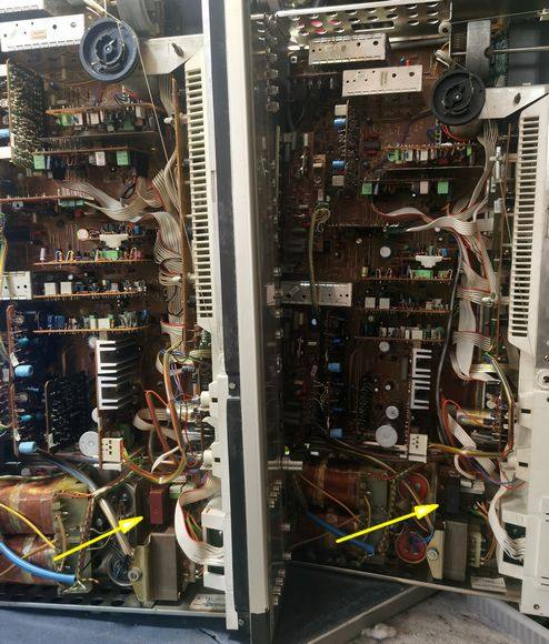 ' data-cke-saved-src='
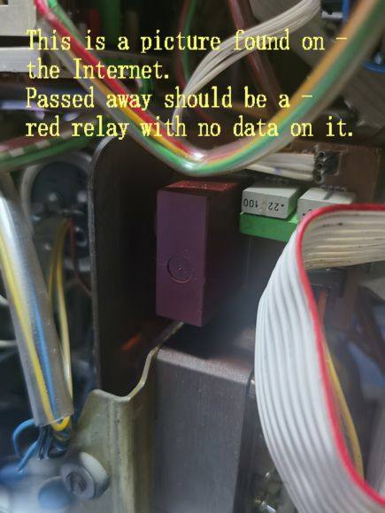 ' data-cke-saved-src='
 '>
'> ' data-cke-saved-src='
 ' data-cke-saved-src=''>
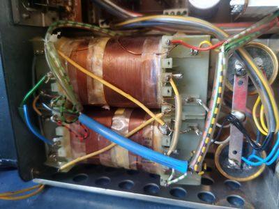 ' data-cke-saved-src='
 '>
'> '>
'> '>
'> '>
'> '>
'> '>
'> '>
'> '>
'> '>
'>