
Hello ,
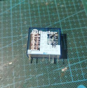
I am buying a new power relay before testing.
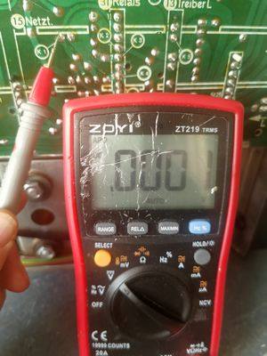
Today I checked the power supply again and found that the power supply is unstable, sometimes there is no DC 15v of K1.
Look at the voltage at several locations of the power supply,
 '>
'>
 '>
'>
 '>
'>
 '>
'>
' '>
'>
K1 has no voltage after several measurements:
 '>
'>
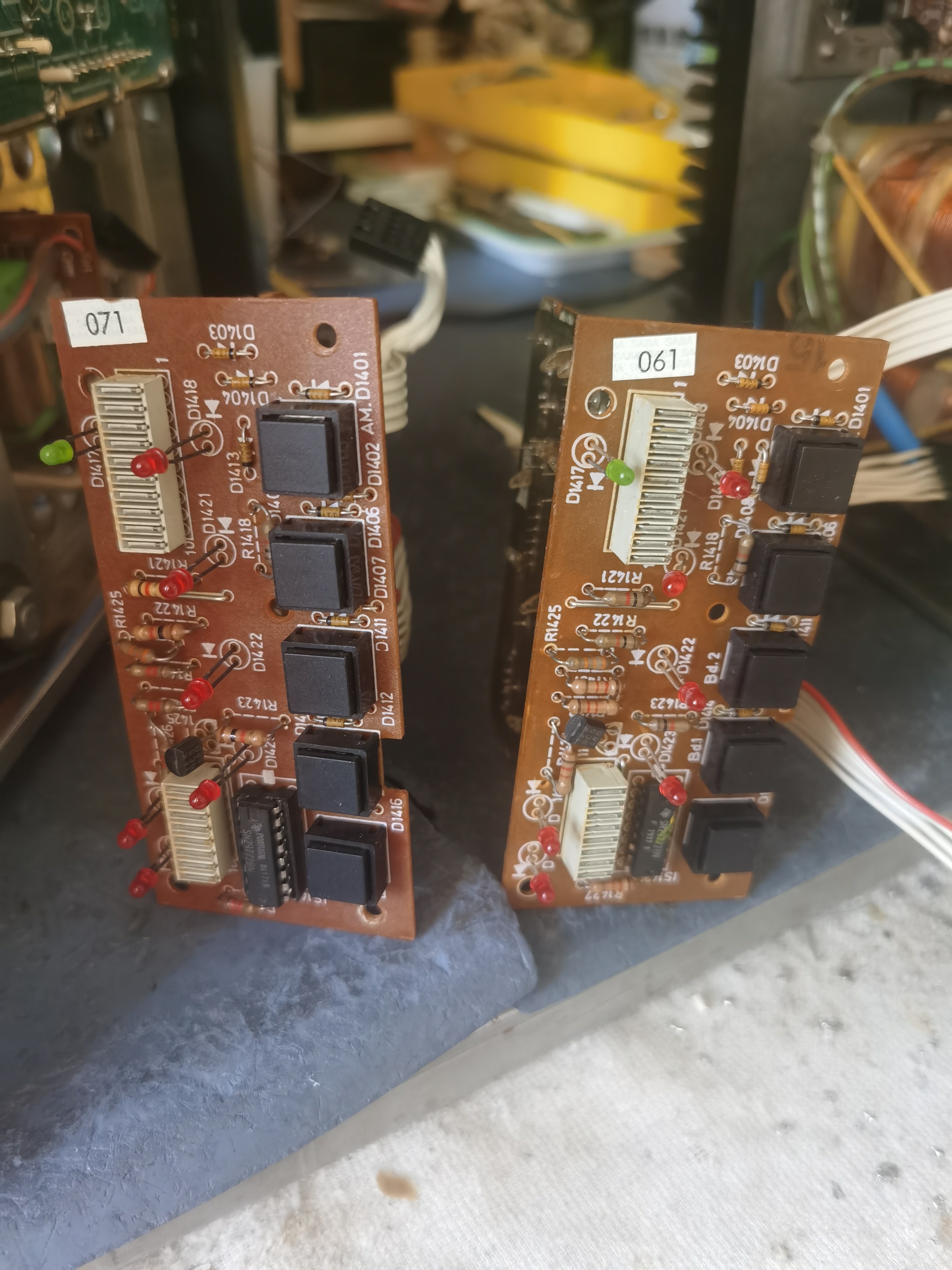
I unplugged the LED connection board, the LED light still flashed.
 '>
'>
I unplugged the LED connection board, the LED light still flashed.
I am buying a new power relay before testing.
Today I checked the power supply again and found that the power supply is unstable, sometimes there is no DC 15v of K1.
Look at the voltage at several locations of the power supply,
'>'>'>'>'
'>K1 has no voltage after several measurements:
'>I unplugged the LED connection board, the LED light still flashed.
'>I unplugged the LED connection board, the LED light still flashed.
Dieser Beitrag wurde bereits 3 mal editiert, zuletzt von „wyx12007cba“ ()
 '
'  '
' '>
'>
 '>
'> '>
'> '>
'> '>
'> '>
'> '>
'> '>
'> '>
'> '>
'> '>
'> '>
'>

