MD-292

      Hello,

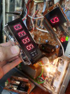
      1. I replaced C567, but the voltage is still abnormal,

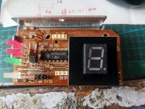
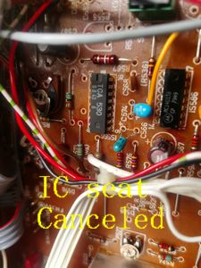
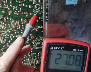
      2. For the convenience of replacing the IC, an IC socket has been added and TCA530 has been replaced. The F2 voltage is normal at 42v, E2-27v, and E3-2.5v

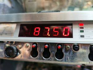
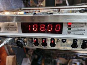
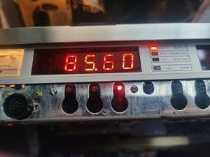
      3. Is the FM frequency 85.6-108.15MHz,and 85.6 normal?

      4. Fault: FM manual tuning is normal, 8 storage stations are abnormal, U2U4U6U8 button is not responding, U1U3U5U7 is normal,

      Please advise, thank you.


      Hello my friend,

      Pls. see the foregoing comment from Michael.

      For adjusting frequency range with the new TCA530:
      Switch to FM, manual tuning, AFC=off
      1. Adjust with P527 to 42,0 V at measurement point F2
      2. Turn tuning dial fully counterclockwise, adjust the digital frequency display with P577 to 87,50 MHz
      3. Turn tuning dial fully clockwise, adjust the display with P572 to 108,00 MHz

      For the pre-set button malfunction:
      It is more difficult for me to say. I would start with replacement of IC623 (MC14430), the address encoder.

      Regards,
      Reinhard
      Thank you friend:

      I have adjusted P527 to adjust the voltage at F2 to 42.0v

      2. Adjusted to 87.50MHz using P577

      3. Adjusted to 108.00 MHz using P572,

      After adjusting, the frequency display is normal, very good!

      4. Regarding the issue of adjusting the preset button fault, I have considered it very difficult. I have come up with a solution to remove the preset button box on my other Saba 201 and install it on 292. The fault still persists, and it is still F2F4F6F8 that does not work. This alternative method eliminates the 292 preset button box fault, proving that it is normal. Can I consider it this way?

      (I have installed the 292 preset button box on 201 again and it works normally, proving that this preset button box is working properly.)

      5. I accept kugel-balu s opinion and plan to remove the TCA530IC seat. For the convenience of not removing it temporarily, I will remove this IC seat after all is completed,

      Please continue to help me find the cause of the malfunction

      thank you.


      Hello my friend,

      Re. the remaining fault, I can only see these possibilities:

      a) IC564
      b) IC561
      c) or a bad plug/connector between the preset button box and main board.

      In detail:
      For U2, U4, U6, U8 the level on line "W" between pre-set board and main board must be "high", but it is "low". Therefore, preset buttons 2,4,6,8 don't work.
      The AM button will also not work in that case.
      Because you could already exclude the pre-set box, the only other parts being involved in the logical switching on line "W" (Code "A" at IC564) are the two ICs 564 and IC561.


      best regards,
      Reinhard

      Dieser Beitrag wurde bereits 2 mal editiert, zuletzt von „oldiefan“ ()

      Hello,

      Your guidance is very accurate. When I checked IC561/IC564, I found that:

      The 12th pin of IC561 is connected to the 3rd pin of IC564 and there is no 5V voltage,

      The 13th pin of IC561 is connected to the 3rd pin of IC564 and there is no 5V voltage,

      The 14th pin of IC561 is connected to the 3rd pin of IC564 and there is no 5V voltage,

      The AM button does not work, and pressing the AM button does not respond,

      I have replaced two IC561 and IC564, but there is still no 5V voltage, indicating that it is not an issue with the IC. Please ask where the fault is and continue to provide guidance,

      thank you.


      Dieser Beitrag wurde bereits 1 mal editiert, zuletzt von „wyx12007cba“ ()

      Hello,

      Please consult the ABCD L, H logical table on the schematic, which I have attached here.
      In your case Pin 14 of IC561 and Pin 4 (=A) of IC621 are always "low". Means A cannot go high. And when A cannot go high, there is no reaction of the buttons AM, U2, U4, U6 and U8.
      If A is low and B, C and D also, U1 is working.
      Because B can go high, while A is low, U3 is working.
      Because C can go high,while A is low, U5 is working.
      Because B and C can go high, while A is low, U7 is working.
      Because D can go high, while A is low, FM-button is working.

      For all the buttons, where A needs to go high, there is no function. So there is only between PIN14 of IC561 and PIN 4 of IC 564 no "high" possible. On the others it is, if the corresponding preset-button according to the logical table is pushed.
      That is already proven because the preset buttons work on U1,U3,U5 and U7 as you wrote. And we know that button FM also works.


      Please click on the picture for enlarging

      Other possibilities?
      A bad connector to the pre-set box?
      or faulty resistor array DS561 or DS563, so that the connection of the respective resistor responsible for the high pulse on A is missing

      I don't see more.

      Best regards
      Reinhard

      Dieser Beitrag wurde bereits 4 mal editiert, zuletzt von „oldiefan“ ()

      I checked every wire in the preset box and found it to be good and normal.

      I also removed the resistor arrays DS561 and DS563, and measured each resistance value of DS561 with a multimeter. The third pin was 4.5k, and the other pins were 4.65k up and down.

      The resistance values of DS563 are all within 4.7k

      I still haven't found the fault... ...

      Hello,

      I didn't mean the wires in the pre-set box to be checked. You had already confirmed before that the pre-set box is fine. I mean the connection to the main board and on the main board and to the indicator board.

      The solder joints and connectors and wires to be checked, all along connection line "W".
      The connection wires are soldered into the main board close to IC 564 and indicated in the service manual on the board layout.
      I have indicated the positions where they are soldered into the board in red:


      click on picture to enlarge

      There must be electrical connection (zero Ohm) between the two red marked solder joints. Please check it.

      Please check also that there is electrical connection (zero Ohm) between Pin 5 of IC622 (in the pre-set box) and Pin 4 of IC 564 (on the main board) and also Pin 5 of IC751 (on the indicator board). All three must be electrically interconnected. Measure with the ohmmeter between the indicated pins of the ICs. By that you cover also all interconnects inbetween.

      Finally, also IC751 on the indicator board is connected to line "W" and could be defective, pulling level A permanently to "low" and thus causing the problem. This IC has not been considered before by me. It might cause the issue, if it is defective and internally shorts Pin 5 to GND.


      click on picture to enlarge


      click on picture to enlarge


      The blue connections are inside the pre-set box and are ok, as you have confirmed by replacing the pre-set box.
      The red connections shall be checked.


      click on picture to enlarge


      Best regards,
      Reinhard

      Dieser Beitrag wurde bereits 9 mal editiert, zuletzt von „oldiefan“ ()

      Hello,

      Your analysis and guidance are very accurate. Follow your red line and search around W to find the dashboard.

      In order to quickly find the fault, I went to my friend's house and opened the Saba 292 he was using. I removed the indicator circuit board and took it back to install it. The U1-U8 display buttons were adjusted normally, indicating that the IC751 on my board was faulty and needed to be replaced. At the same time, I compared and measured the voltage on the two circuit boards, further confirming that the IC was faulty, and finally found the fault.

      Thank you very much to my oldiefan friends. They have patiently guided me step by step, which has strengthened my confidence in hands-on maintenance and taught me many methods for repairing electronic products. I am 65 years old this year, and you have enriched my elderly life. Once again, thank you! At the same time, I would like to express my gratitude to kugel-balu and friends, and wish you all the best.

      I will continue to follow the forum and love it. Thank you, friend!


      Dieser Beitrag wurde bereits 1 mal editiert, zuletzt von „wyx12007cba“ ()

    • Benutzer online 1

      1 Besucher