
MD-292
-
-
Hallo Klaus,
Sind die Versorgungsspannungen auf Anhieb korrekt vorhanden? Besonders MP F2 (42V), G2 (+15V) und G3 (bei FM +15V)?
Ggf. diese Netzteilelkos ersetzen: saba-forum.dl2jas.com/bildupload/292b.JPG
C913 und C916 (im Stereodekoder) ersetzen. Sind meist trocken!
C474, C484 (auf Buchsenplatte) ersetzen.
Spannungen an Messpunkten D1 und D3 (4,5V DC) prüfen.
Wenn danach immer noch defekt:
Signaldurchgang durch IC458 (MOSFET Schalter) prüfen.
Gruß
Reinhard
Dieser Beitrag wurde bereits 2 mal editiert, zuletzt von „oldiefan“ ()
-
Hallo Reinhard,
danke für die Tipps,
ich habe gestern dem Besitzer einen MT-201 als Leihgerät gegeben. Sobald er ihn ausgetauscht hat bekomme ich den MD-292 wieder.
Er hatte ihn zwischenzeitlich abgeholt und gestern vergessen ihn wieder mitzubringen :-(.
Ich melde mich mit den Fortschritten wenn es weitergeht.
Grüße
Klaus -
So, jetzt habe ich den MD 292 wieder bekommen.
Habe die entsprechenden Sachen geprüft / getauscht und noch einmal an vielen Stellen nachgelötet weil die Digitalanzeige auch schon wieder aus was :-(. Dann habe ich ihn an einen anderen Verstärker angeschlossen. Im Moment funzt er.
Jetzt testeten wir alles mit dem MI 215.....schaun mer mal.
Danke erst einmal an alle
Grüße
Klaus -
Hello everyone,
I have encountered a Saba 292 that cannot be used. After my efforts, it is now able to receive radio signals normally and the sound is also very good. There is still a malfunction that I cannot complete. Please ask my friends for guidance. Thank you.
But my machine screen can only use 79-97.95. Please take a look at the pictures I took,
I have encountered this fault for the first time and I don't know where to adjust it.
Please give me some guidance.


Dieser Beitrag wurde bereits 1 mal editiert, zuletzt von „wyx12007cba“ ()
-
Is the difference between here broken and normal working 10,7 MHz?
AndreasWas bedeutet DL2JAS? Amateurfunk, www.dl2jas.com -
-
Please answer the question!
It can be a problem with the intermediate frequency.
If so, it will be a hint to solve the problem.
AndreasWas bedeutet DL2JAS? Amateurfunk, www.dl2jas.com -
I have encountered a Saba 292 and there is a malfunction that I cannot complete. Please ask my friends for guidance. Thank you.
Fault: FM can only be tuned within this range of 79-97.95. Please refer to the picture.
I have encountered this fault for the first time and I don't know where to adjust it. Please give me some guidance. -
Hello my friend!
You described the fault: "You can only tune between 79 MHz and 97.5 MHz".
The so called "tuning voltage" needs to be checked in a first place. This voltage is indicated in the service schematic as "UAbst. 3...27 V". You can measure it at pin 3 of the FM-Tuner Module.
Please measure it when the unit is switched to "manual tuning" and "FM" and with the tunig wheel turned fully contercklockwise and a second time when turned fully clockwise. You should measure 3 V DC and 27 V DC, respectively.
Please measure also DC voltage at measurement points E2 (27 V) and E3 (3 V).
If you measure different voltages, please report.
C415 may be leaky, or IC564 could be faulty or TCA530 (IC566) could be defective or a varicap in the fm tuner might be defective...we'll find out.
Best Regards
Reinhard
Dieser Beitrag wurde bereits 3 mal editiert, zuletzt von „oldiefan“ ()
-
-
Because the tuning voltage is not right, the tuner does not reach the correct frequencies.
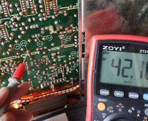
1. Please measure the voltage at the measurement point F2. It shall be +42 V.
If you can confirm, that you have +42 V at F2, continue as follows:
2. Replace C415 (3.3 µF 35V) - it may suffer from leakage. This is just to be sure that it is not this tantalum capacitor which causes the issue of too low tuning voltage.
3. Remove the two screws at the bottom under the FM-tuner box and then pull out the fm-tuner box. Then repeat the measurement of the tuning voltages at measurement points E2 and E3, as described before.
Don't worry that the frequency display is not displaying correctly anymore when the tuner box has been pulled out.
- Is there still the wrong (too low) voltages at E2 and E3 (FM manual tuning is selected, AFC = off) when the FM tuner box is pulled out and the tuning wheel is fully turned counterclockwise / clockwise?
4. If the voltage is still far too low (as in your photographs before) when the fm-box is removed, the defect is not in the fm-tuner box. That will direct us to the tuning voltage generation and regulation in a next step.
5. However, if the voltages are correct when you have pulled out the fm-tuner box, we shall focus on the varicap diodes inside of the FM tuner box in a next step.
Please report.
Best Regards
Reinhard
Dieser Beitrag wurde bereits 1 mal editiert, zuletzt von „oldiefan“ ()
-
My friend gave very accurate guidance and reported the measurement results:
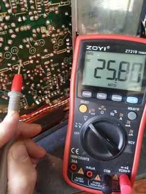
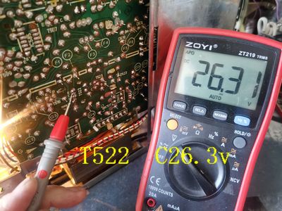
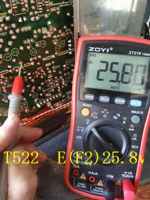
F2 is only 25v, where is the problem?
D506 59.6v, T522 C26.3v, T522 E(F2)25.8v

Dieser Beitrag wurde bereits 1 mal editiert, zuletzt von „wyx12007cba“ ()
-
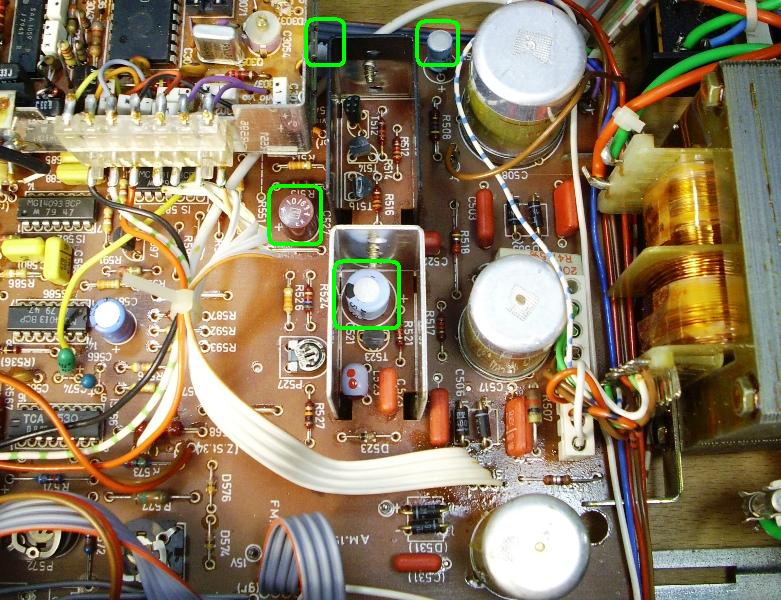
Please replace C527 and C521. Both might have excessive leakage current, C521 partial short to ground, because it is very likely defective.
C521 is heated by the U-shaped heatsink of T522. Therefore its lifetime is reduced. Replace C521 by a 110°C electrolytic cap, if possible.
Best regards,
Reinhard
-
-
Hello,
1. C726 (220 µF) for buffering the supply for the headphone amplifier may have an internal short, pulling the +42 V down.
2. Solder joints of T522 may be defective. Please resolder T522.
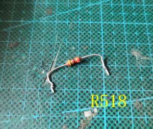
3. In the power supply, resistivity of R518 may have become too high. Or R518 has been replaced and a too high value was used. Be aware that the value 22 k shown in the service schematic is wrong! Correct is 22 Ohm, not 22 kOhm for R518!
4. Zener diode D523 (12 V Zener voltage) may have become leaky. Please check if the zener voltage over D523 is 12 V.
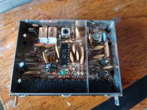
5. Finally, if the wrong voltage still persists, please show a photograph of the stereo decoder module that is in this MD 292.
Reason: SABA made two versions of the decoder. One has two filter cans/channel (older version), the other one has three filter cans/channel (= correct one for the MD292). There is a difference in the wiring for the voltage supply between these decoder types. PIns 12 and 13 of the 2 cans/channel module are internally connected but are separate on the 3 cans/channel module. That can be detrimental.
Putting the wrong decoder (with two filter cans/channel) into the MD292 without further modification, causes the +15 V FM voltage (G3) becoming directly connected to +42 V (F2) via resistor R445 (560 Ohm). Thus, there will be 42 V on one side and 15 V on the other side of R445, hence 27 V over R445. This will cause a current of about 50 mA through R445, corresponding to 1.3W which could pull the 42 V down.
Sometimes a person who does not know about this difference puts the 2 can/channel stereo decoder module in a receiver, which was made for the 3 cans/channel because the original module did not work properly anymore (i.e. it became misaligned or a capacitor became bad).
Best Regards
Reinhard
Dieser Beitrag wurde bereits 3 mal editiert, zuletzt von „oldiefan“ ()
-
My report:
1. Replaced C726 (220uf, 100uf on the original machine);
2. Dismantle R518 and find that this resistor is broken. Replace it with a new 22R (shown in the circuit diagram as 22K), and the F2 voltage is normal at 42v,
3. Remove the D523 Zener diode, which is also broken and has been replaced.
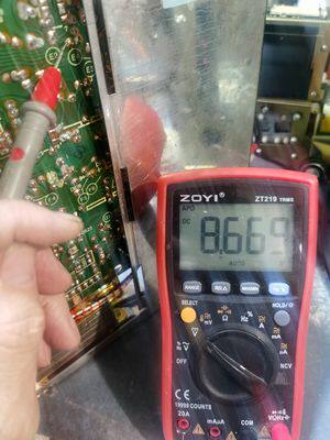
4. The voltage of E2 and E3 is still abnormal, E2-9.9v, E3-0.9v. This fault needs to be pointed out,
5. The stereo decoder is original and has not been replaced, and the numbering is consistent.


-
Hello,
Your last photograph does neither show the stereo decoder nor is it the fm-tuner box. You pulled out and photographed the IF-amplifier box which has nothing to do with the defects.
Please reassure yourself, which module is the fm-tuner box. If you are uncertain, take photographs and ask.
We are moving ahead in small steps. After having now the principal voltage restored in the power supply, we will find out by further measurements, what causes the faulty tuning voltage.
Please follow the following steps as outlined already above:
1. Replace C415 (3.3 µF 35V) - it may suffer from leakage. This is just to be sure that it is not this tantalum capacitor which causes the issue of too low tuning voltage.
2. Remove the two screws at the bottom under the FM-tuner (front-end, mixer-) box and then pull out the fm-tuner box. Then repeat the measurement of the tuning voltages at measurement points E2 and E3, as described before.
Don't worry that the frequency display is not displaying correctly anymore when the tuner box has been pulled out.
- Is there still the wrong (too low) voltages at E2 and E3 (FM manual tuning is selected, AFC = off) when the FM tuner box is pulled out and the tuning wheel is fully turned counterclockwise / clockwise?
3. If the voltage is still far too low (as in your photographs before) when the fm-box is removed, the defect is not in the fm-tuner box. That will direct us to the tuning voltage generation and regulation (i.e. TCA530) in a next step.
4. However, if the voltages are correct when you have pulled out the fm-tuner box, we shall focus on the varicap diodes inside of the FM tuner box in a next step.
Please report.
Best Regards
Reinhard
Dieser Beitrag wurde bereits 3 mal editiert, zuletzt von „oldiefan“ ()
-
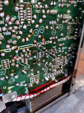
1. It's a bit messy. Just after turning on the power, the F2 voltage is abnormal again, F2-25v
2. I disconnected the connection from F2 to IC566 (TCA530). As shown in the picture, if I disconnected this connection, the F2 power supply would normally be 42V, and if I connected this connection, it would become 25V,
3. Replaced C415 (3.3 µ F 35V),
4. After disconnecting the connection from F2 to IC566, F2 is 42v. Measure the frequency modulation box 2 and stereo decoder 4, and the power supply is normal.
May I replace IC566? Could it be that other parts are faulty? Please provide guidance,
thank you.

-
