SABA 9241 digital Falsche Anzeige

      SABA 9241 digital Falsche Anzeige

      Hallo zusammen.
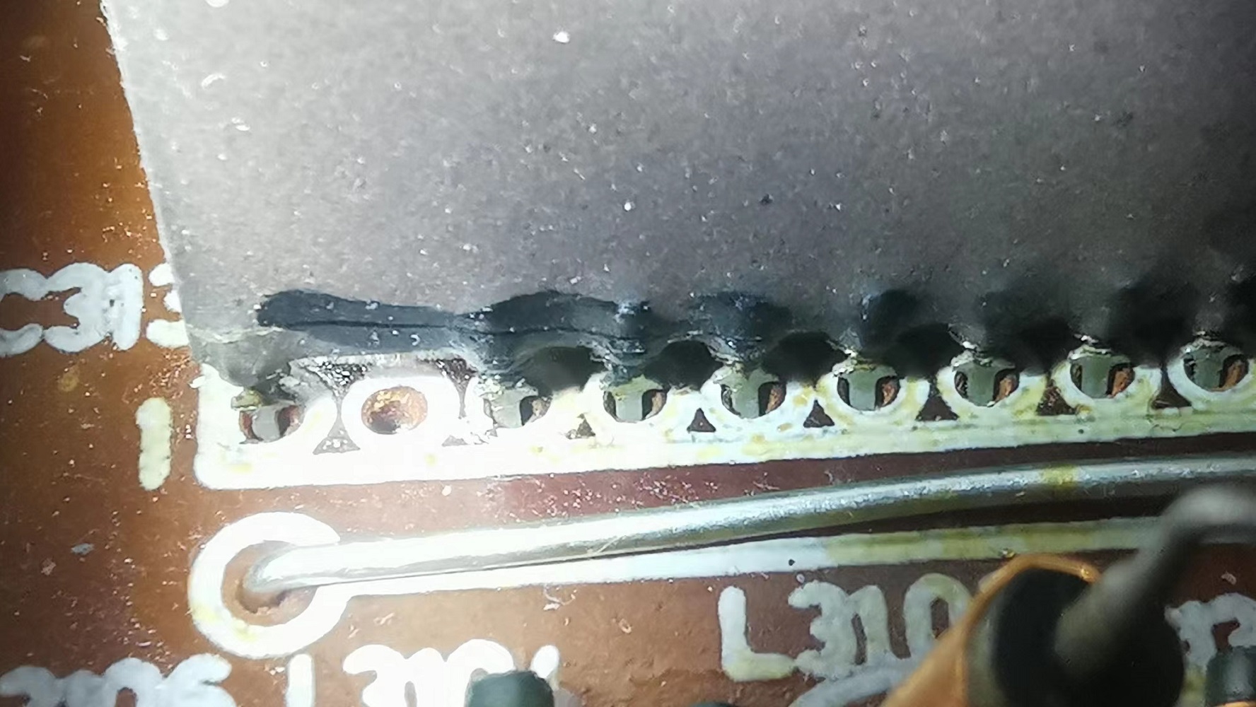
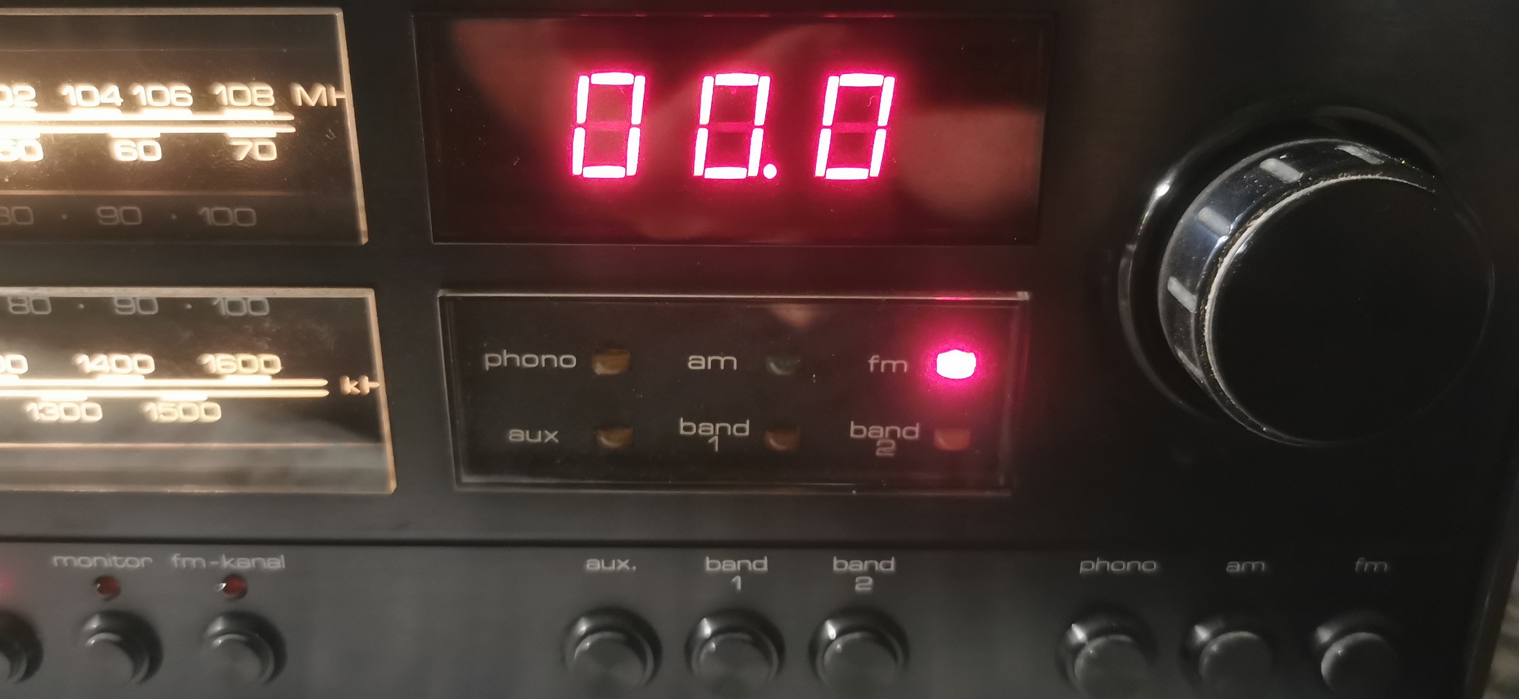
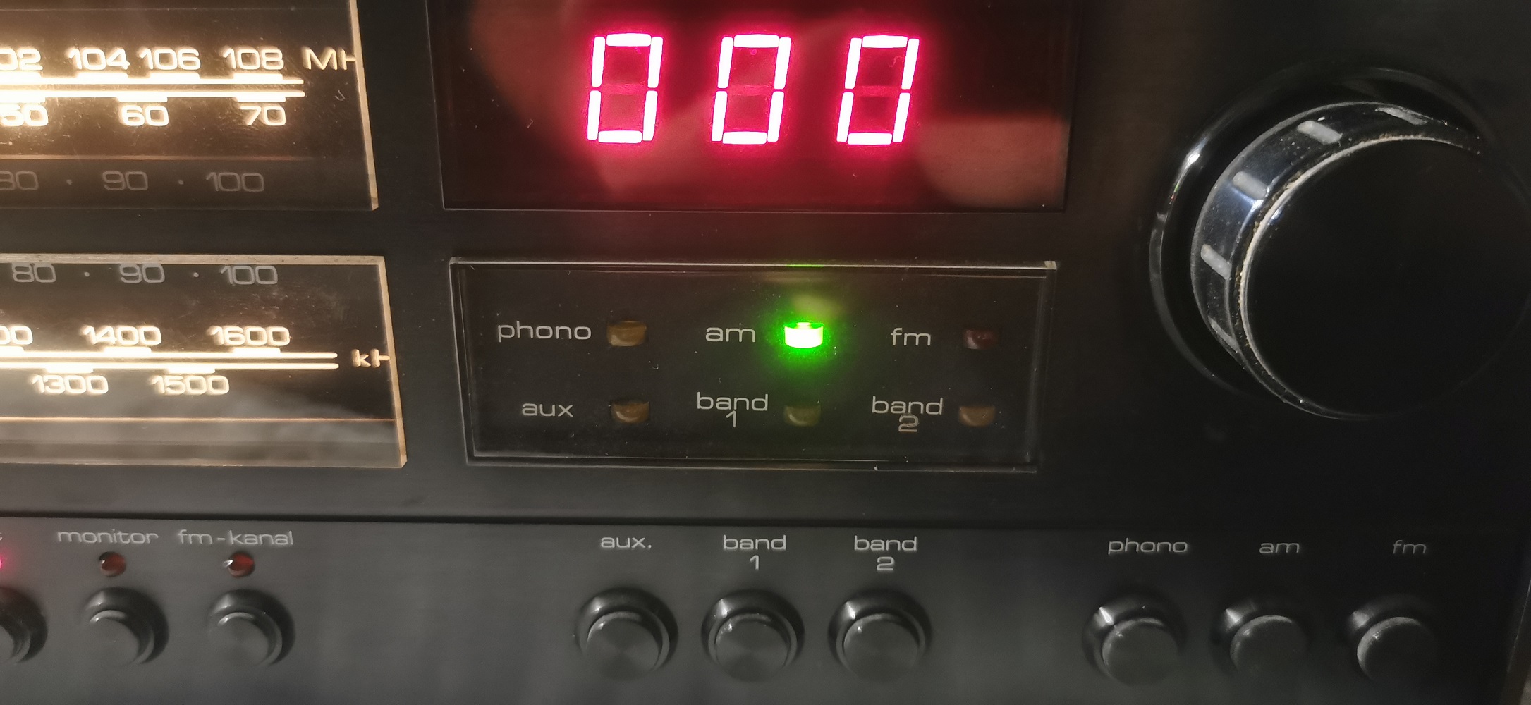
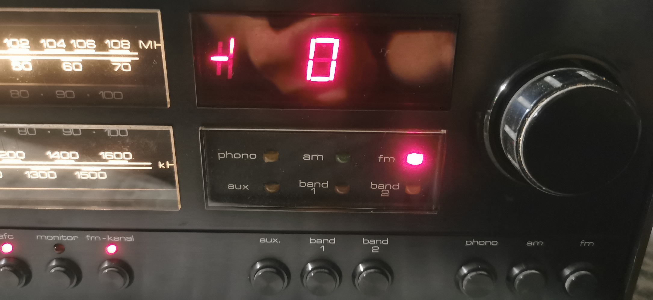
      Ich bin ein Freund aus China. Ich habe eine Saba 9241 digital. Nach dem Test kann das Gerät normal in AM und FM funktionieren, aber AM zeigt 000 und FM zeigt 00,0 an. Bitte sehen Sie sich das Bild an, das ich gesendet habe, +9V und -17V Spannung. Das ist normal. Ich öffnete die Verpackung der Anzeigekomponente und stellte fest, dass der AO 808-Pin gesprungen zu sein schien, bin mir aber nicht sicher, ob das etwas damit zu tun hat. Aufgrund fehlender Informationen weiß ich nicht, wie um es zu lösen, und ich habe nicht den gleichen Fehler wie ich im Forum gesehen! Es gibt keine Beiträge im Forum über den gleichen Fehler dieser Maschine. Bitte teilen Sie mir die Reparaturmethode mit, danke!

      Da ich kein Deutsch spreche, verwende ich Google Translate und versuche, so klar wie möglich zu sein.

      Grüße aus China!


      Dieser Beitrag wurde bereits 14 mal editiert, zuletzt von „xiao0507“ ()

      Hello friend,

      please find attached the schematics for the counter.
      In a first step you shall confirm
      a) that you find at the fm- and am inputs of the counter box the corresponding mixer frequency, respectively
      b) that you find the correct voltages of +5 V and -12 V behind the voltage stabilizer ICs LM320K and LM309K

      The electrolytic caps
      C3102
      C3103
      C3107
      C3112
      C3044
      shall be replaced.

      The swords which are connecting both boards in the counter must all be present and shall fit tightly.


      Best Regards
      Reinhard


      Xiao0507, verstehst Du Englisch?
      Xiao0507, do you understand English?

      English is the best language for foreign members, many members understand it.
      Many translators have problems to translate technical terms into German.
      I invite you to use English, our second language in the forum.
      Englisch ist die sinnvollste Sprache für ausländische Mitglieder, verstehen hier viele Mitglieder.
      Viele Übersetzungsprogramme haben Schwierigkeiten, technische Fachbegriffe ins Deutsche zu übersetzen.
      Du darfst gern hier in Englisch schreiben, unsere zweite Sprache im Forum.

      Andreas, Administrator
      Was bedeutet DL2JAS? Amateurfunk, www.dl2jas.com

      oldiefan schrieb:

      Hello friend,

      please find attached the schematics for the counter.
      In a first step you shall confirm
      a) that you find at the fm- and am inputs of the counter box the corresponding mixer frequency, respectively
      b) that you find the correct voltages of +5 V and -12 V behind the voltage stabilizer ICs LM320K and LM309K

      The electrolytic caps
      C3102
      C3103
      C3107
      C3112
      C3044
      shall be replaced.

      The swords which are connecting both boards in the counter must all be present and shall fit tightly.

      saba-forum.dl2jas.com/index.ph…1587f82e80b4bde44427b031e

      saba-forum.dl2jas.com/index.ph…1587f82e80b4bde44427b031e

      saba-forum.dl2jas.com/index.ph…1587f82e80b4bde44427b031e


      Best Regards
      Reinhard


      Thanks Reply!
      a) FM and AM signals are available, and the radio can work normally.
      b) +5V and -12V voltages are also available.
      The electrolytic caps
      C3102
      C3103
      C3107
      C3112
      C3044
      Has been replaced.
      The AO 810 was damaged and has been repaired. It can currently display 0000, but cannot display the radio frequency. The 1.1V voltage at pin 27 of AY-5-8100 is abnormal and is now 5V.
      Thanks for the drawings!
      The wrong voltage at pin 27 might indicate that either AY-5-8100 or SN7402 (or both in worst case) could be defective.
      Normally, the current (about 4.7 mA) through R3043 (820 Ohm) causes a voltage drop of 3.9 V (from 5 V to 1.1 V) across this resistor. However, if there is too little or no current through R3043 then there will be little or no voltage drop and you measure in that case 5 V supply voltage at pin 27 of AY-5-8100, which is also connected with pin 13 of SN7402.

      I believe that the input pin 27 of AY-5-8100 has a high input impedance. Thus, I would be more suspicious about IC SN7402. But I nust confess that I never had this defect and therefore my practical experience is limited in this case.

      Optional additional test:
      You may want to assure that the frequency-counter-signal (rectangular wave form) arrives at pin 6 of SN7402.
      1. Set FM to 89 MHz (or anywhere close to it) = fm(set)
      2. Check with the oscilloscope that you see the counter signal with its frequency fo at Pin 9 of the IC MC10116. fo is by 10.7 MHz higher than the set frequency:
      fo = fm(set) + 10.7 MHz
      3. Check with the oscilloscope that you see the counter signal with its divided frequency fo/10 at Pin 6 of IC SN7402.

      Best Regards
      Reinhard

      Dieser Beitrag wurde bereits 10 mal editiert, zuletzt von „oldiefan“ ()

      oldiefan schrieb:

      The wrong voltage at pin 27 might indicate that either AY-5-8100 or SN7402 (or both in worst case) could be defective.
      Normally, the current (about 4.7 mA) through R3043 (820 Ohm) causes a voltage drop of 3.9 V (from 5 V to 1.1 V) across this resistor. However, if there is too little or no current through R3043 then there will be little or no voltage drop and you measure in that case 5 V supply voltage at pin 27 of AY-5-8100, which is also connected with pin 13 of SN7402.

      I believe that the input pin 27 of AY-5-8100 has a high input impedance. Thus, I would be more suspicious about IC SN7402. But I nust confess that I never had this defect and therefore my practical experience is limited in this case.

      Optional additional test:
      You may want to assure that the frequency-counter-signal (rectangular wave form) arrives at pin 6 of SN7402.
      1. Set FM to 89 MHz (or anywhere close to it) = fm(set)
      2. Check with the oscilloscope that you see the counter signal with its frequency fo at Pin 9 of the IC MC10116. fo is by 10.7 MHz higher than the set frequency:
      fo = fm(set) + 10.7 MHz
      3. Check with the oscilloscope that you see the counter signal with its divided frequency fo/10 at Pin 6 of IC SN7402.

      Best Regards
      Reinhard


      Thanks Reply!
      I have replaced the SN7402 and the problem remains the same.
      I tested the new SN7402 and the old MC10116, and as you said, the signals are all normal.

      If any of pins 8, 9, and 12 of SN7402 is high, pin 13 should be high.

      Are SN7493 and SN74176 broken?

      Is there any program written inside AY-5-8100?

      best regards

      xiao0507 schrieb:


      I have replaced the SN7402 and the problem remains the same.
      I tested the new SN7402 and the old MC10116, and as you said, the signals are all normal.
      If any of pins 8, 9, and 12 of SN7402 is high, pin 13 should be high.

      Are SN7493 and SN74176 broken?

      Is there any program written inside AY-5-8100?

      best regards


      Not sure, if SN7493 or SN74176 is broken. Bth interact with SN7402. Also the AY-5-8100 could be broken.
      The AY-5-8100 does not have a program written, therefore it could be easily replaced.

      Best regards
      Reinhard

      oldiefan schrieb:

      Zitat von xiao0507: „
      I have replaced the SN7402 and the problem remains the same.
      I tested the new SN7402 and the old MC10116, and as you said, the signals are all normal.
      If any of pins 8, 9, and 12 of SN7402 is high, pin 13 should be high.

      Are…


      Thank you very much for your reply!
      I replaced the AY-5-8100 and the machine is working normally and the display is completely normal.
      Again, thank you!