Freiburg 7 -- Relay resistor wattage

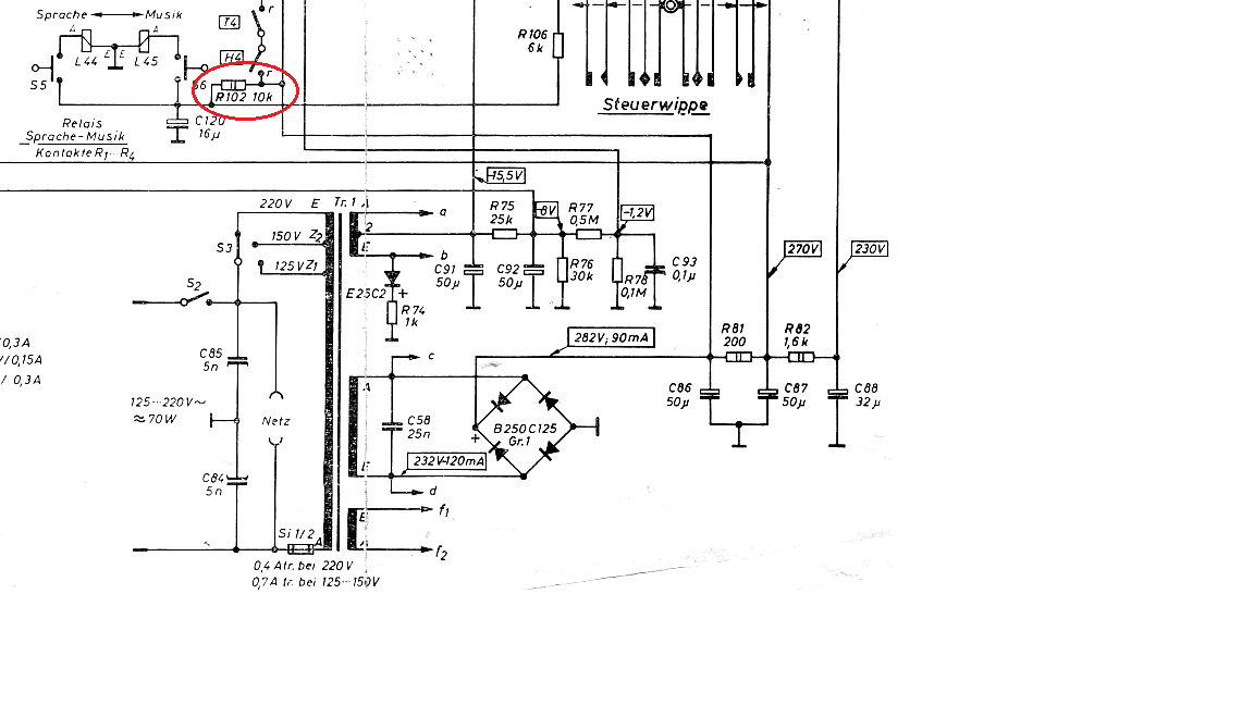
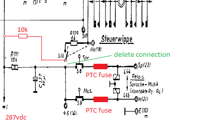
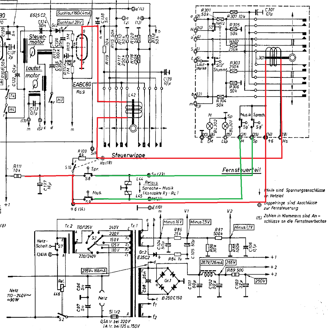
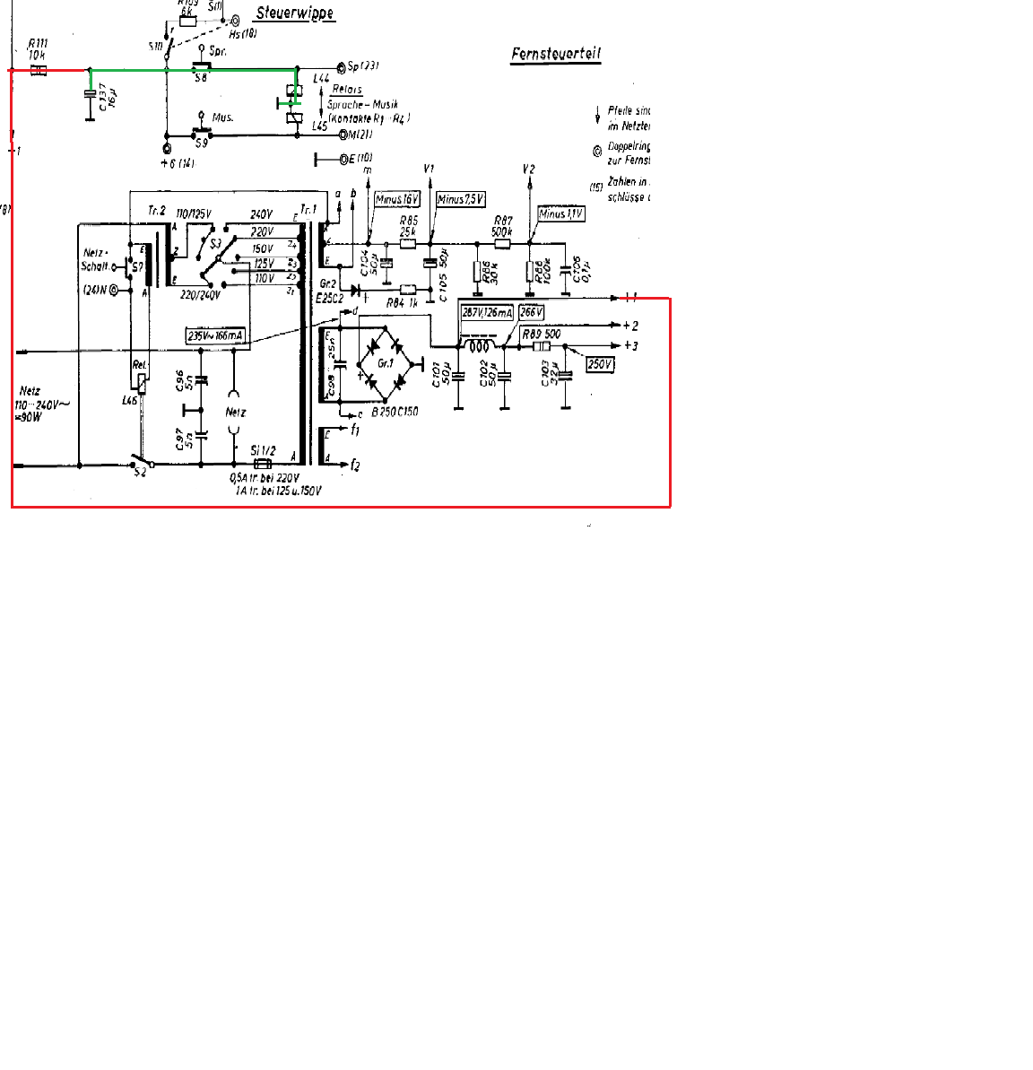
      I have discovered a "toasted" (burnt) resistor in the Freiburg 7 I am restoring. The resistor, R111, is a 10k, 2 watt resistor that controls the charging of C137 that provides the current necessary to switch the Music/Speech relays. When one pushes the "Sprache" or "Musik" button, C137 discharges through the relays. Once one ceases to push the button, C137 will recharge through R111. During the time the button is pushed until C137 recharges (or nearly recharges) the current through R111 will exceed the wattage rating of this resistor. Since the duty cycle is so low, and wire wound resistor can tolerate overload conditions for a short while, this is okay. However, I can foresee my future yet-to-be-born grandson or granddaughter pushing this button for a long time (and I suspect this is what happened in the distant past). The worst case situation with someone holding his finger on the button shows 8.2 watts (287x287/10000) being dissipated by R111.

      Question: What size resistor (wattage) should I use for R111? Should it be a wire wound type or can I use a film type?

      Yes, I discounted the resistance of the relay, since it is so low. I agree with Peter's value. Frankly, it is an unsafe condition and constitutes a fire hazard, albeit, a very low one. And one I am not losing any sleep about. However, I am replacing the 2 watt, R111 resistor with a 10 watt wire wound one.

      By the way, the same situation occurs in the Meersburg 7, shown here:

      Interesting point! - we have had reports here about the 10K resistor being burnt several times before and I always thought the coil of the automatic-control-switch was the culprit. By the way it's DC-resistance is about 10K.

      So probably the speech/music relais are to blame here!

      My suggestion would be to seperate the relais from the automatic-control-circuit, give them their own 10K resistor and fit in a self-resetting-PTC-fuse with appropriate voltage / current for each relais.

      Maybe this could solve the issue.

      Unfortunately I can't contribute any drawings or pictures at the moment since I'm using an unstable 80KBit GPRS connection here in South Tyrol - no broadband available :(
      Achim
      Thanks, Achim. My solution, at the moment, is to just up the wattage of R111 to 10 watts (or R102 in the Meersburg). That way even if one keeps their finger on S8 or S9 all day resistor R111 will not burn (but it will get hot). That, by the way, does not trouble the relays at all. Once C137 has discharged through the relays, the current through the relays will be minimal (29 ma). Power dissipated by the relay will be less than 100 milliwatts.

      I think what you are suggesting is this:


      The problem I see is that one wants a large current flow when the S8 or S9 is initially push -- C137 will dump all its current through the relay, causing it to switch. The PTC fuse may prevent this. C137's discharge is just what one wants to cause the relay to switch and does not lead to R111's overheating. R111's overheating is due to just this 29 ma of quiescent current (and eventually the recharging of C137 once the button is no longer pushed).

      Let me know if the diagram is what you were thinking.

      Regards, Jim
      Hi guys,

      I just had another idea: What if we leave the 10 Kohms resistor there for the automatic control only and connect the two relais and C137 via let's say a resistor of 47 Kohms.
      This would result in a far lower current so the resistor only needs a low wattage, the load for the 287V- would be quite small if the buttons are being pushed for a long time.

      The only limitation would be that you will have to wait a little before you can switch from music -> speech or speech -> music back again.

      I could live with that ;)
      Achim
      Achim, that would work. Power dissipation by the 47k resistor would be about 1.75 watts worst case, so a 2 watt resistor would be sufficient. The time constant of the 47k resistor and C137 is about 0.75 seconds -- that should be fast enough.

      Using separate resistors for the automatic control and the resistors has the benefit of allowing one to switch from music to speech (or vice versa) without interrupting a station search that is in progress. With the current design, pressing the button will stop the search since C137 dumps its voltage. But I don't think anyone ever switches while a search progress anyways.

      Having said that, I went ahead and bought a 10 watt 10k wire wound resistor which is physically smaller (same diameter, just shorter) than the original 2 watt resistor. There is more than adequate space to mount the resistor so that nothing comes in contact with it. Once I get this radio up and running I will check it out.
      Hi Jim,

      I don't like the idea of a 10 Watts resistor in this place too much.
      We alredy had coils of automatic-switches with ground fault here, so if there´s a defective coil in a remote control, there's a permanent load of more than 8 Watts that isn't a desirable state for the power supply.
      So if the two circuits are seperated and the automatic control has it's 10K 2 Watts resistor the resistor will limit this load by being grilled to death.
      Achim
      Hi Achim,

      I agree it is an area of concern. For the record, here is the circuit including the "Fernsteuerteil".


      Assuming the circuit is working correctly, if the remote control is connected, switch S10 is open and the coil in the remote control takes the place of R109 (6k resistor). If a search is started either from the front of the radio or from the remote control, the appropriate coil will be energized (the coils are in series) until the EABC80 lets go. The concern is if the coil in the remote control develops a short to ground thereby puting the full load (287 vdc) across R111 (the 10k 2 watt resistor). This would cook R111.

      A short like this in L301 will not by itself draw enough current to pop the fuse. I have, for the moment, installed a 10 watt resistor for R111. This is sufficient to handle a worst case scenario such as above, but is it the best solution? If one adds a separate 10k resistor to run just the automatic search function, then the problem still exists. A short to ground in L301 will still cook the newly added 10k resistor. One could try adding a small (say 15 to 20 ma) fuse in series with the 10k. In normal operation, just 4ma of current flows through this resistor. A short to ground in L301 will increase this to about 29ma.

      I am happy to report that I turned the radio on for the first time today (after major - major rework -- all paper & electolytic caps replaced, both motors rebuilt since they were siezed, dials restrung since they were incorrectly done, etc, etc. Following your work, Achim, helped a lot.) and it mostly works -- all bands function, but the search does not (motor runs, but the problem seems to be with the circuit that develops the -16vdc, -7.5vdc, and -1.1vdc -- are about 1/4 what they should be. Not sure why.). The 10 watt resistor works and switching Music/Speech back and forth does not make it too hot.

      Anyhow, I am going to give it more thought. I have to stop on it at the moment as my wife and I are off to the states. My oldest son is getting married next Friday (making the same mistake the old man did), so I will not get a chance to particpate on this forum until we get back.
    • Benutzer online 2

      2 Besucher