Three questions about SABA 9140

      Three questions about SABA 9140

      Hello everyone! I'm from China. I might not express myself very clearly, but I have an issue with my radio and would appreciate your help. Thank you!

      I recently got a 9140 machine, but it is not working properly, mainly due to the following three problems.
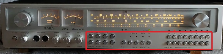
      1、After the power is turned on, all buttons cannot be locked. The indicator light will light up when pressed and go out when released, which means that the button function cannot be selected.
      2、When I hold down the button with my hand to maintain the radio function, the radio broadcast sound can be heard from the speaker, but it is very hoarse. The sound of the two speakers is the same. The same problem applies to other functions. Is this problem related to the first question?


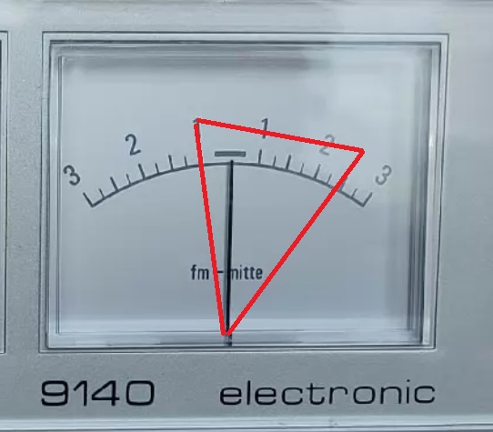
      3、The range of movement of the hands of the FM-mitte watch is to the right. How can this be corrected to a balanced left and right swing position?


      Dieser Beitrag wurde bereits 5 mal editiert, zuletzt von „xiao0507“ ()

      Hi,

      maybe a good start would be to check the voltages around the Functions and FM-channel switching units. But I doubt, that this will be the only issue with your unit. A fourtyfive year old piece of electronics needs in most cases some treatment of contacts and potentiometers, check and repair of cold solder joints, and check of all supply voltages, that they are all within normal range. Only when this all is done, it makes sense to start systematic failure search and repair.

      Regarding the FM-Mitte indicator: This behaviour can have several reasons, i.e. ZF-frequency shift due to aged ZF-piezo filters or a detuned L318 or even simply a dejusted P2027. I would propose to start with the more serious issues first. To adjust the ZF-selection and demodulation section it is necessary to use special equipment, i.e. FM signal generator, oscilloscope and some experience with that.

      Best regards,
      Christian
      Bilder
      • FM_Switching.jpg

        280,74 kB, 1.120×781, 10 mal angesehen
      **************************************************
      2 + 2 = 5 (für extrem große Werte von 2)

      chriss_69 schrieb:

      Hi,

      maybe a good start would be to check the voltages around the Functions and FM-channel switching units. But I doubt, that this will be the only issue with your unit. A fourtyfive year old piece of electronics needs in most cases some treatment of contacts and potentiometers, check and repair of cold solder joints, and check of all supply voltages, that they are all within normal range. Only when this all is done, it makes sense to start systematic failure search and repair.

      Regarding the FM-Mitte indicator: This behaviour can have several reasons, i.e. ZF-frequency shift due to aged ZF-piezo filters or a detuned L318 or even simply a dejusted P2027. I would propose to start with the more serious issues first. To adjust the ZF-selection and demodulation section it is necessary to use special equipment, i.e. FM signal generator, oscilloscope and some experience with that.

      Best regards,
      Christian


      Thanks for your reply! Perhaps I did not explain the issue clearly enough, so I have attached supplementary photos. None of the buttons on the machine can stay pressed; the indicator lights do not turn on after pressing. This means the buttons fail to lock into place, rather than just the FM radio function being faulty. Additionally, the tuning needle’s full range of movement sits toward the right side of the dial, yet the frequency readings it shows appear to be accurate.

      kugel-balu schrieb:

      Some of the pushbuttons are non-locking. If the LED does not light, best first check what Christian suggested. Quite often, the voltages are missing, because the power supply module is faulty.

      Michael


      Thanks for your reply! For all the buttons shown in the picture, the corresponding LED lights up only while the button is held down and turns off as soon as you release it. This indicates that the control unit is malfunctioning. I have already inspected the power supply module, and its output voltages are all normal.
      The the next logical step is to check the switching voltages at the corresponding transistors of the push buttons. For the time being, doing so on one of the fm buttons is enough. Question: What are the readings on the marked test points in the schematic above with and without pressing down the button.
      **************************************************
      2 + 2 = 5 (für extrem große Werte von 2)

      chriss_69 schrieb:

      The the next logical step is to check the switching voltages at the corresponding transistors of the push buttons. For the time being, doing so on one of the fm buttons is enough. Question: What are the readings on the marked test points in the schematic above with and without pressing down the button.

      I ran a test by pressing the FM button. The red figures show the voltage when the button is unpressed, while the purple ones indicate the voltage when pressed. There is a noticeable difference, as marked on the attached picture.

      Dieser Beitrag wurde bereits 1 mal editiert, zuletzt von „xiao0507“ ()

      Neu

      Hi

      at first glance the voltage at the emitter of T1042 is too low. It should be approx. 23 volts And it should not change much during switching. It is derived from the stabilized FM tuning voltage via zener diode D2092. Either the source of this voltage is the problem or somewhere downways is a current loss.

      Tomorrow I am back home and can have a closer look at the circuit. Actually I only have my mobile phone available and this makes it difficult to analyse what is going on here.

      Best regards,
      Christian
      **************************************************
      2 + 2 = 5 (für extrem große Werte von 2)

      Neu

      After having a more detailed look on the schematic I still would suggest, that there is an issue with the 23 v supply voltage. This are my thoughts:


      The channel switching system gets two different voltage supplies:
      Blue box: +12: 23 Volts, derived from 31 Volts stabilized output voltage from the FM Tuning Voltage Module.
      Red box: +1a: 29,5 Volts, derived from 45 Volts from the voltage supply module.


      +13 is also of interest, it connects all emitters of the NPN-transistors together and via R1066, which has 330 ohm, to Ground.

      From the measured voltages with and without pressing a button it can be concluded, that the connections +1a and 13 are working as expected. It can also be concluded, that at least the two transistors T1041 and T1042 are working.
      Not in order is still the voltage at +12. It should be 23 Volts and rock stable, no drop must occur when one of the buttons is pressed. I would suggest therefore an issue with
      • bad connection between Anode of Zener Diode D2092 and the Emitter of T1042
      • faulty Zener Diode D2092
      • faulty regulation system for 31 V voltage - i.e. defective TCA530
      • faulty connection of the tuning voltage module to the 45 V supply line.
      Xiao, could you please check, if the voltages change, when you press one of the buttons at the following points:
      • Anode of D2092 - should be 23 V
      • Kathode of D2092 - should be 31 V
      • Base of T517, accessible via connector 7 of the tuning voltage module - should be 31,7 volts
      • Supply voltage of the Tuning voltage module, directly at the module, at R504. - should be 45 V
      None of these voltages should drop when pressing a button. I would expect the fault between the last stable point and the first point with a drop.

      Best regards,
      Christian
      **************************************************
      2 + 2 = 5 (für extrem große Werte von 2)

      Dieser Beitrag wurde bereits 2 mal editiert, zuletzt von „chriss_69“ ()

    • Benutzer online 5

      5 Besucher